
FREE PHOTOCRAFT · SOLIDCRAFT
SolidCraft Beginner Tutorial: Model, Resize and Export a Mounting Plate
Follow a worked SolidCraft v0.12.0 mounting plate example with real screenshots, sketch constraints, parametric extrusion and downloadable design, recipe, STEP and STL files.
SolidCraft v0.12.0 · Independent guide · October 16, 2026
The part and prerequisites
We built this part by driving SolidCraft v0.12.0 on Windows x64 through MCP. The screenshots show the actual application window. Use the complete recipe to rebuild the same part, then inspect its sketch and timeline in the desktop application. No AI client setup is required for this page.
Target dimensions: 60 mm wide, 30 mm high, 4 mm thick, with two 6 mm through-holes centered at (10,15) and (50,15) mm. Units are millimeters. The sketch lies on XY and extrudes along positive Z.
First follow the Windows portable setup. In the extracted folder, type powershell in the address bar and press Enter. Run the commands below in that PowerShell window. Save mounting-plate.json beside solidcraft-cli.exe and confirm the filename does not end in .txt.
1. Rebuild and open the design
.\solidcraft-cli.exe run .\mounting-plate.json --save .\my-plate.solidcraft --out .\my-plate.step --out .\my-plate.stl
.\solidcraft.exe .\my-plate.solidcraft
A successful first command creates my-plate.solidcraft, my-plate.step and my-plate.stl. The second command opens the editable design. If a command fails, read its error before proceeding. The following steps explain how the recipe builds the model.
2. Constrain the rectangle and holes
The recipe defines width=60 mm, height=30 mm and thickness=4 mm, then creates PlateProfile. Its rectangle spans (0,0) to (60,30). The bottom edge length references width; the right edge references height. Origin coincidence and horizontal/vertical constraints anchor its position and orientation.
The circles use x=10 mm and x=width−10 mm, with y=height/2 and diameter=6 mm for both. This keeps the right hole 10 mm from the right edge after resizing. The resulting sketch has zero degrees of freedom (DOF), meaning it is fully constrained. Approximate visual placement is not equivalent.
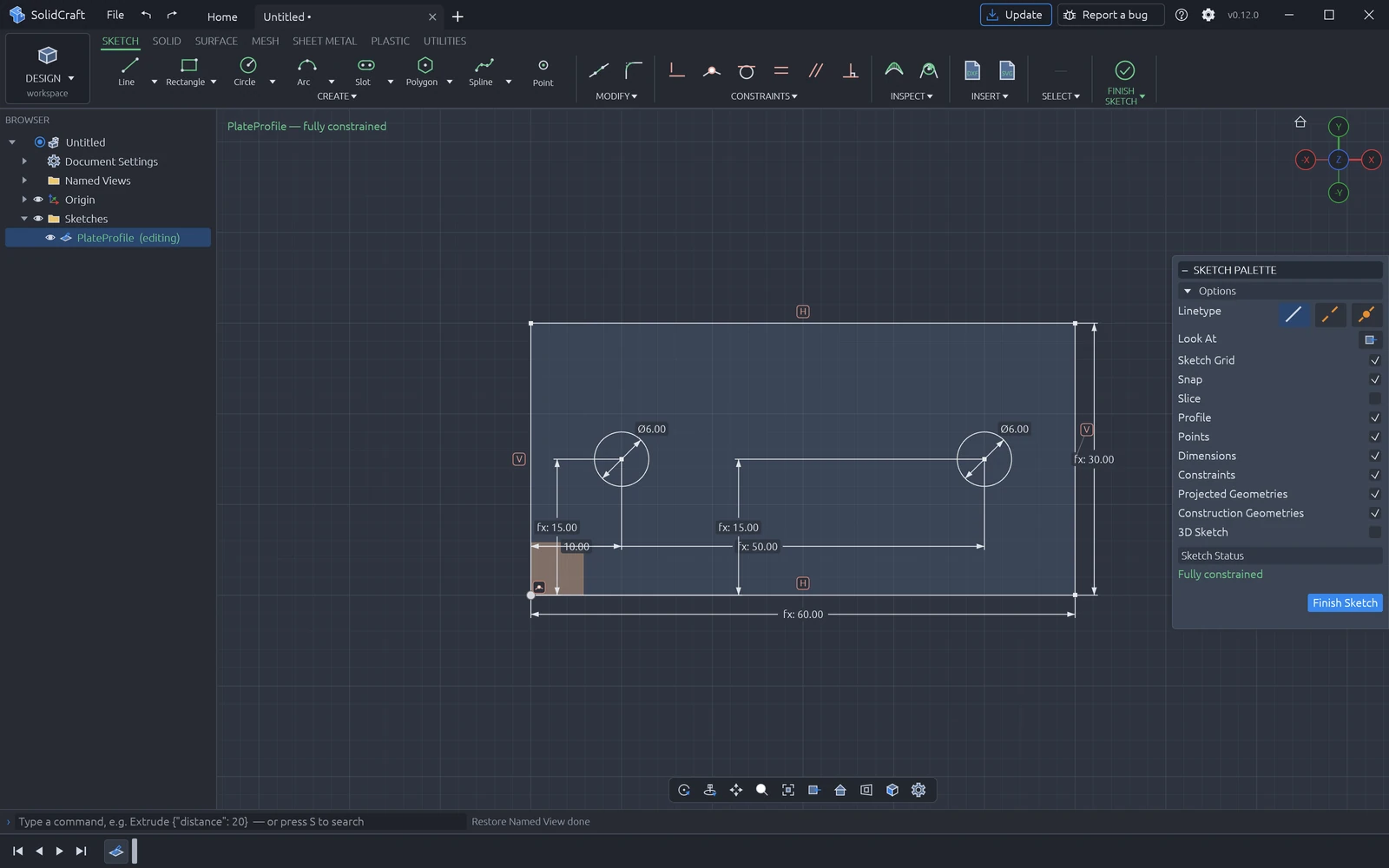
3. Extrude the outline and keep the holes
After finishing the sketch, solid.extrude uses thickness as its distance and selects the rectangle outer boundary l1, l2, l3 and l4. The inner circles remain holes, rather than becoming filled disks.
{"command":"solid.extrude","params":{"distance":"thickness","profiles":[{"curves":["l1","l2","l3","l4"]}],"body_name":"MountingPlate"}}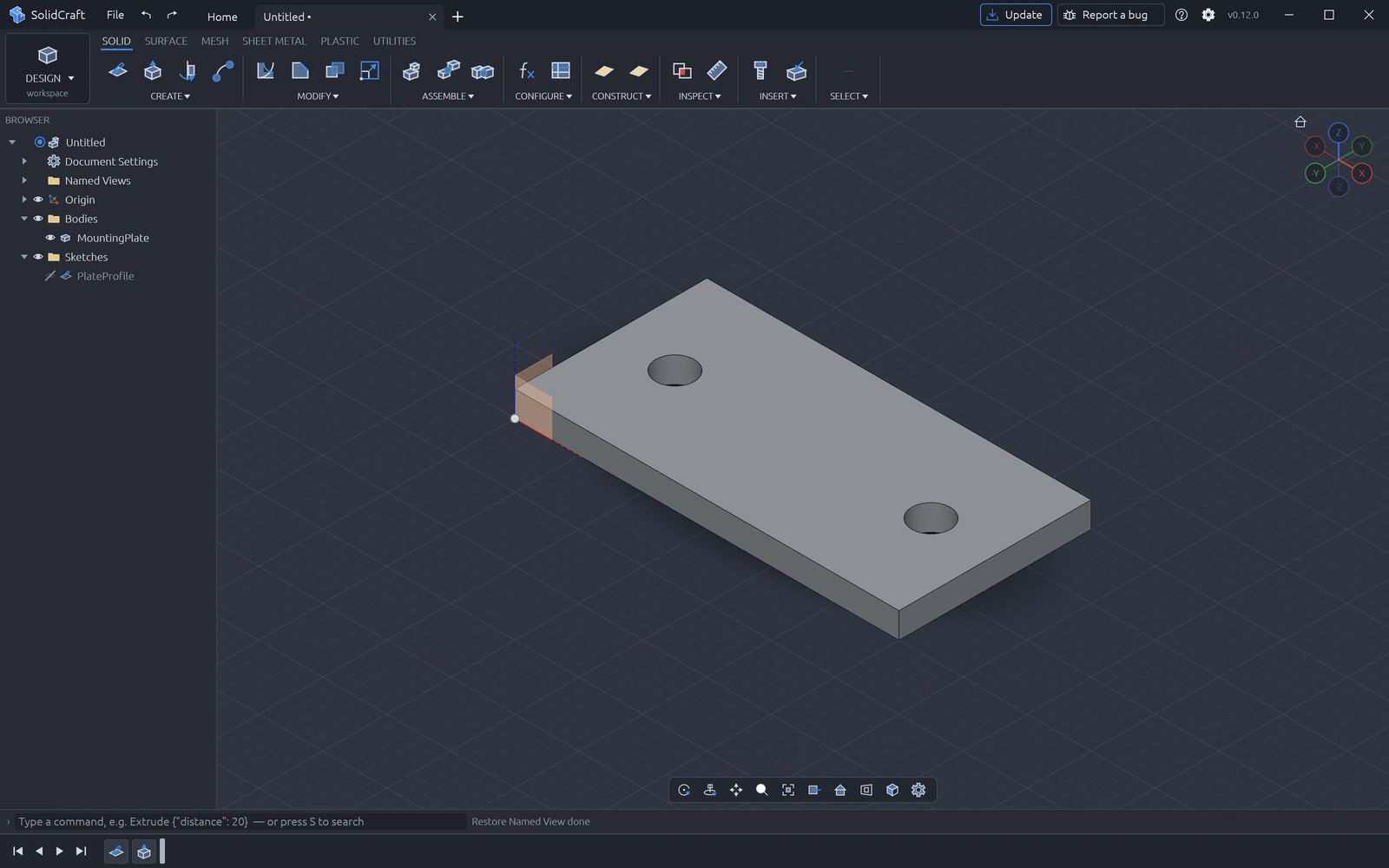
4. Change the width from 60 to 80 mm
Save the following complete content as resize.json in the same folder. In Notepad, paste it and choose Save As → All files, with the name resize.json. Then run the PowerShell command below.
{"commands":[{"command":"parameters.change","params":{"name":"width","expression":"80 mm"}}]}.\solidcraft-cli.exe run .\resize.json --in .\my-plate.solidcraft --save .\my-plate-80.solidcraft --out .\my-plate-80.step
.\solidcraft.exe .\my-plate-80.solidcraftThe result should measure 80 × 30 × 4 mm. The right hole center moves from x=50 to x=70 mm, preserving the 10 mm side margin. The left hole remains at (10,15). This checks that sketch expressions and the extrusion actually rebuild with the parameter.
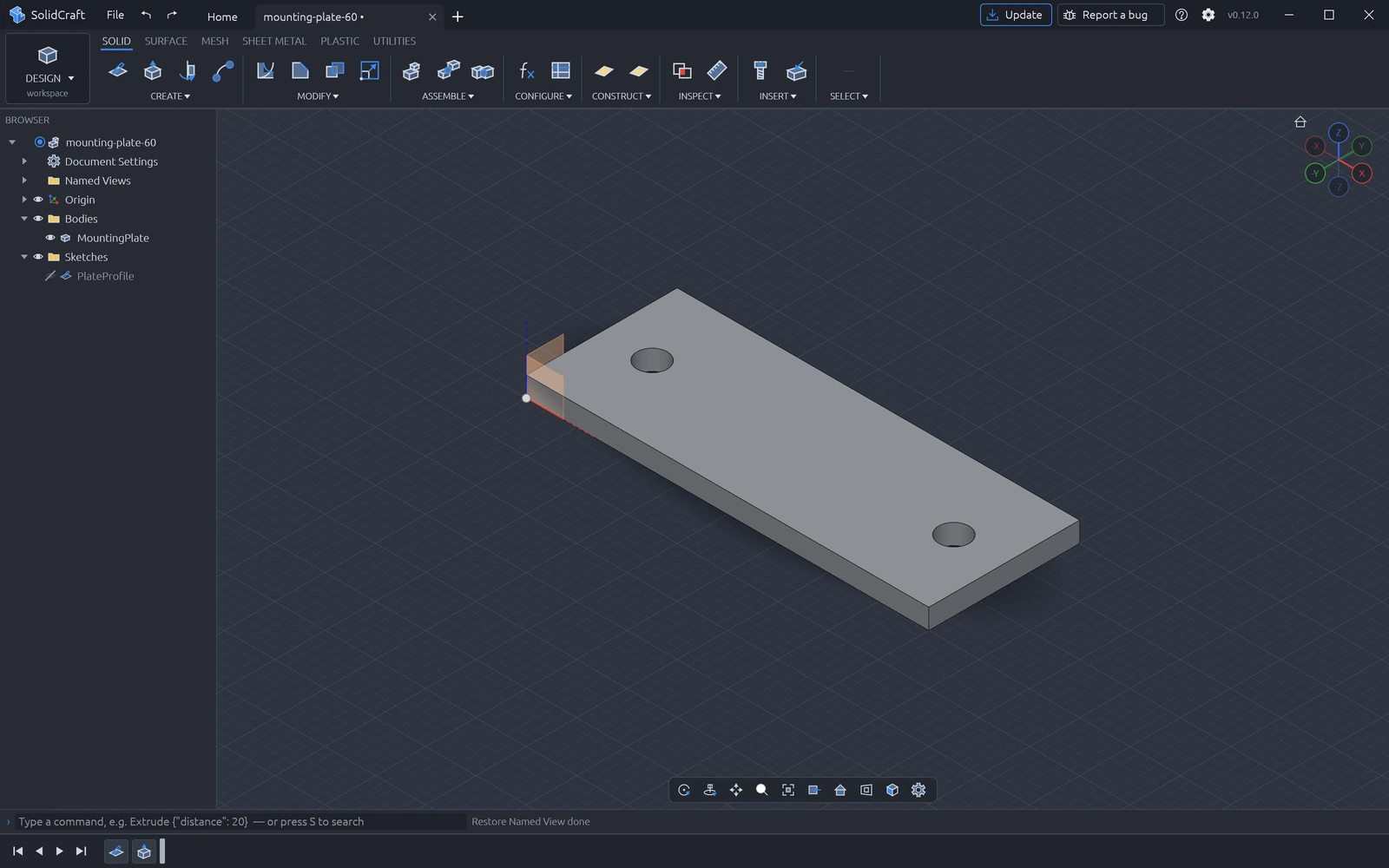
5. Measure, reopen and check the export
.\solidcraft-cli.exe eval .\my-plate.solidcraft --json-out .\measures-60.json
.\solidcraft-cli.exe eval .\my-plate-80.solidcraft --json-out .\measures-80.json
.\solidcraft-cli.exe eval .\my-plate.step --json-out .\step-check.json
On a small screen, scroll horizontally inside the table.
| Check | 60 mm version | 80 mm version |
|---|---|---|
| Body count | 1 | 1 |
| Bounding box / mm | 60 × 30 × 4 | 80 × 30 × 4 |
| Volume / mm³ | 6973.843 | 9373.843 |
| Right hole center / mm | (50, 15) | (70, 15) |
Subtracting two cylindrical holes from the rectangular plate gives analytic volumes of approximately 6973.805 and 9373.805 mm³. Both measured values differ by less than 0.001%. We also reopened the 60 mm editable design and reimported its STEP file, checking body count, bounding box and volume.
The native .solidcraft file preserves editable history. STEP exchanges solids and does not promise recovery of the original feature timeline. STL is a triangle mesh. Successful export is not a slicing or physical-print test; check units, orientation and manufacturing tolerances separately.
Troubleshooting and next steps
If the extrusion fills the holes, check that profiles selects the rectangle outer boundary. If the right hole does not move, check its horizontal expression: width - 10 mm. Do not repair a parametric relationship by dragging the hole after each edit.
Sources and version
Sources checked October 16, 2026. Examples target SolidCraft v0.12.0; the latest release and main-branch documentation may change. This is an independent guide.
Official GitHub · v0.12.0 release notes · Official getting-started guide · Sketches and constraints · MCP tool documentation